Drainage in England and Wales is covered by Approved Document H, which deals with both foul water – from toilets and from basins, baths, sinks, washing machines and so on – and surface water, that is rain run-off.
All foul water drainage systems carry it from the building to an underground sewer pipe a cesspool a septic tank or a waste-water treatment system. Public sewers are not considered in Approved Document H directly though so guidance from and consultation with the local water authority should be sought when connecting to or building near or over such a sewer.
- to a public sewer
- to a private sewer communicating with a public sewer
- to a septic tank or other waste-water treatment plant
- to a cesspool
When properties are isolated, or it is impractical to connect to the public sewer due to constraints such as ground conditions and topography, building control surveyors presented with proposals for foul water drainage should ensure it discharges to the third or fourth options on this list. If drainage is connected to a septic tank ,cesspool or treatment plant, bear in mind that surface water should not be connected to that drain. Underground drainage systems are divided into two types.
Combined system: this is the most common type of drainage in the UK, where foul water and rainwater are carried in the same underground pipes. The practical advantages are that, first, the rainwater helps to clean the pipework, minimising blockages; and second, less pipework is required although pipe diameter may need to be increased.
Separate system: with this arrangement, there are distinct sewer pipes for foul water and rainwater.
The Building Regulations separate the requirements for foul and surface water, and water authorities discourage combined systems because they can overload the drainage system or produce an increased amount of water to treat. New developments are thus required to provide a separate system of drainage up to the point of connection with a combined sewer.
Drainage should be planned alongside foundations and the floor plans of the building, ensuring that it doesn't conflict with other services or the building foundations. Care should be taken that the foundations are not undermined when the plan is to lay drainage in parallel with them, while foundations should always sit below the drains' invert level – that is, the bottom of the inside of a drainage pipe or inspection chamber – so as not to apply building loads to the pipework.
Drainage should also be laid to falls, that is a gradient allowing water to flow freely. Mains foul water drains of 110mm diameter, the typical drain size, carrying discharge from multiple soil stacks and buildings may be laid at a fall of not less than 1:80 that is 12.5mm fall per metre of length. However, branch drains from individual gullies, sanitary fittings or soil stacks should be laid at a steeper gradient of 1:40 or 25mm fall per metre. Mains surface water drains of 110mm diameter that carry discharge from multiple rainwater pipes may be laid at a fall of not less than 1:100, that is 10mm fall per metre. Branch drains from individual rainwater pipes should be laid at a steeper gradient of 1:50 o,r 20mm fall per metre.
When bedding and backfilling drainage, the material dug from the trench may be suitable to surround the pipe, but it will need to be examined to ensure that it meets the required standard. Bedding material must be properly compacted, with shallow hollows made to accommodate the pipe sockets and 100mm cover provided above the pipe itself. Material that has sharp edges such as broken bricks is not suitable. When the dug material is not appropriate for backfill, a nominal 10mm-sized aggregate complying with BS 882: Part 2 Specification of Aggregates must be spread evenly on the trimmed trench bottom before the pipes are installed.
Pipe materials
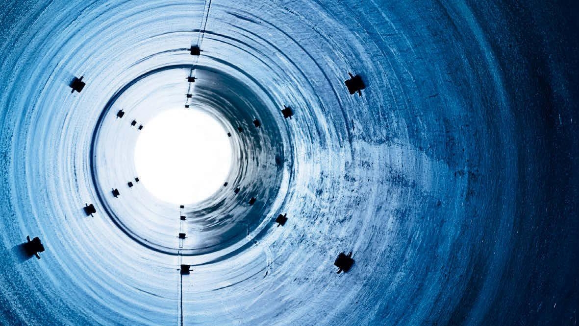
In the past, drainage pipes have been made from a variety of materials, including pitch fibre, vitrified clay, uPVC, concrete, glass-fibre-reinforced plastics, iron and asbestos cement. However, most new domestic drainage is constructed using flexible plastic pipes or rigid clay ones, usually 110mm in diameter, or 150mm and 225mm in diameter respectively for public sewer pipes.
Clay drainage pipes date back to Victorian times. Their inherent strength means they are more durable and less likely to deform under loads than plastic. They are also highly resistant to frost and rodents, and can often be laid directly into a trimmed and formed trench known as class D bedding, whereas plasticware must be surrounded by a selected small gravel or pea-shingle.
Granular material used for pipe bedding and sidefill must conform to BS EN 1610. Manufacturers promote the environmental advantages of clay by claiming that it uses less energy to produce as well as requiring fewer aggregates for bedding and backfilling.
However, the most common material used for underground drainage today is 110mm plastic pipes. The advantage of these is that they are relatively cheap compared to clay, are frost-resistant and flexible, and can remain watertight. While they allow for small amounts of movement without fracturing, though, excessive pressure from loads or ground movement may cause them to deform. Therefore, they must be surrounded by a good bedding material such as pea shingle to provide support and prevent the pipe from cracking. As building control professionals, we will often get to see the results of drainage that has been laid incorrectly and poorly planned.
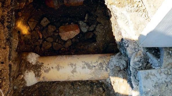
While drains are permitted to run through a foundation they still need to be provided with movement joints to prevent fracture under load and should not be in direct contact with the foundation. When a drain is cast in a strip foundation it needs to be removed and re-laid to the correct falls with the incorrect section removed and filled.
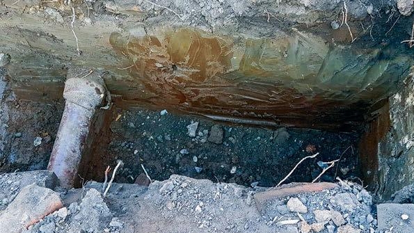
Foundations cast for an extension often cross existing drainage. When building control applications are made, the applicant should declare to the building control body whether there is a drain within 3m of the proposed works. Any drain found in this zone is subject to a build-over agreement, which can be obtained from the local water authority.
The photo below shows a foundation to an extension where a previously unknown foul drain has been exposed. The builder had to expose the drain along the length of the foundation and then protect it before casting the foundation, which had to be lower than the invert level of the drain. Drain protection such as this can take multiple forms, but often uses timber formwork or ridged insulation to encapsulate the pipe.
Surveyors should also be aware of regional requirements for drainage. In the North West of England, applications are subject to the requirements of the Cheshire Brine Pumping (Compensation for Subsidence) Act 1952, which deals with the protection of foundations from mineral attack and subsidence. Surveyors should always engage with the water authority to check whether specific legislation such as this applies locally.
Alternatives to mains rainwater drainage
In areas where mains drainage cannot be used, an alternative needs to be sought for the disposal of surface water. Soakaways are a traditional way of disposing of surface water from buildings distant from a suitable public sewer or watercourse; however their efficiency depends on ground conditions. To determine suitability a percolation test needs to take place in accordance with Part H and guidance from the BRE.
- within 5m of a building or road
- within 2.5m of a boundary
- in an area of unstable land in ground where the water table reaches the bottom of the soakaway at any time of the year
- near any drainage field, drainage mound or other soakaway so that the overall capacity of the ground is exceeded, and the effectiveness of any drainage field is then impaired
- where any contamination in the run-off could result it the pollution of a groundwater source
Soakaways must have sufficient capacity to store immediate run-off from roofs and hard surfaces, and the water must then be able to disperse into the surrounding soil quickly enough for the soakaway to be able to cope with the next sustained period of rainfall.
There are many means of forming a soakaway. They can be created from square or circular pits, filled with rubble or lined with dry-jointed masonry or perforated concrete ring units. Larger areas are generally served by lined pits, trench-type soakaways or those constructed from specialist proprietary units. It should be expected that a domestic, rubble-filled soakaway may need to be renewed about every ten years.
"New developments are required to provide a separate system of drainage up to the point of connection with a combined sewer"
- first, an adequate soakaway or some other adequate filtration system
- second, where a soakaway is not reasonably practical, a watercourse
- finally, where a watercourse is not reasonably practical an appropriate sewer.
Internal drainage boards
An internal drainage board (IDB) is a local public authority that manages water levels. These boards are an integral part of managing flood risk and land drainage in areas of special need in England and Wales, and they are geographically concentrated in Cambridgeshire, Kent ,Lincolnshire, Norfolk, Nottinghamshire, Somerset and Yorkshire.
IDBs' work involves the maintenance and improvement of watercourses and related infrastructure such as pumping stations, weirs, sluices, culverts and embankments. Under the Land Drainage Act 1991, each IDB holds a power of supervision over all matters relating to water level management and can prohibit the obstruction of watercourses in their district. Anyone constructing or altering a weir, bridge, embankment, culvert or similar obstruction must first seek the boards consent before undertaking works.
Many of the IDBs also have a series of by-laws relating to the management of watercourses, and can designate features and structures in their district that relate to managing flood risk. This designation prevents the owners from altering, removing or replacing the structure or feature without an IDBs consent.
Control competencies
The processes discussed above and the assessment of the design risks and remedial work count as evidence towards the following competencies.
Building control inspections: if the work involves site inspections to ensure that installations meet relevant performance requirements, and also entails the ability to observe, assess and take action against contraventions on site, it would normally demonstrate Level 2 of the competency. Where remedial works are required and reasoned advice is provided, the candidate could achieve Level 3.
Building pathology: understanding defects analysis and explaining building fabric failure to identify potential risks to offer advice, and to highlight incorrect drainage installations, drainage failure and its causes, as well as the remedial works required, can demonstrate achievement of Level 3.
Construction technology and environmental services: work can be used to show understanding of the design and construction process and being aware of construction solutions to problems.
Works progress and quality management: work can demonstrate knowledge of construction technology techniques and their relevance on site.
John Miles MRICS is a technical and business development manager at Assent Building Control johnmiles@assentbc.co.uk
Related competencies include: Building control inspections, Building pathology, Construction technology and environmental services
Images © John Miles